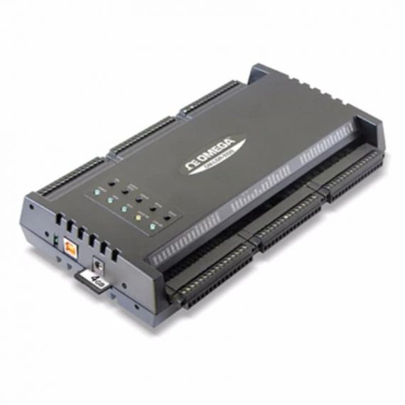
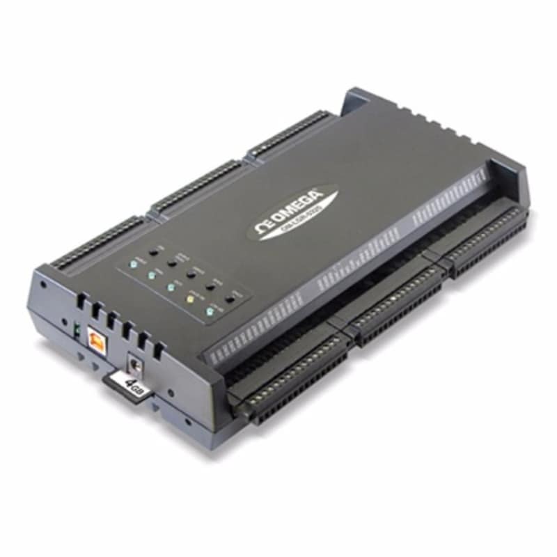
The High speed voltage data logger of the OM-LGR-5320 Series are high speed, standalone data loggers for analog and digital signals. Each module offers 16 analog inputs, 16 digital inputs, one single Form C relay (0.5A) digital output for triggering/alarming, and four counter/encoder inputs. These devices allow users to collect high-speed correlated analog and digital data without a computer. OM-LGR-5320 devices perform high-speed, correlated measurements, up to 200 kS/s, directly to a Secure Digital (SD) or SDHC memory card. Utilizing the advanced analog and digital triggering options, users can collect data to monitor systems and events without dedicating a PC. The OM-LGR-5320 loggers include easy to-use DAQLog software to configure the devices and retrieve data via the USB interface or SD memory card.
Three models are available in the OM-LGR-5320 Series. The OM-LGR-5325 features up to ±10V analog inputs, 100 kS/s sampling, four conventional counter inputs (non-quadrature), and singlechannel trigger modes. The OM-LGR-5327 features up to ±30V analog inputs, 200 kS/s sampling, four quadrature encoder inputs, and multi-channel trigger modes. The OM-LGR-5329 includes all the functionality of the OM-LGR-5327 plus isolated digital inputs.
Analog Input
16SE/8DE analog inputs are included on each data logger. The OM-LGR-5325 features multiple analog input gain ranges up to ±10V. The OM-LGR-5327 and OM-LGR-5329 add a ±30V analog input range for increased measurement capability. Each data logger provides 16-bit resolution.
Correlated, High-Speed Sampling
The OM-LGR-5327 and OM-LGR-5329 can sample input data at up to 200 kS/s while the OM-LGR-5325 offers a 100 kS/s sample rate. Each module can sample all analog, digital, and counter data synchronously, making it easy to compare time between all channels.
Configuration, Data Storage, and Retrieval
Each data logger can be configured through the SD memory card or via the on-board USB port. Simply configure the logging session with the included DAQLog software. All logging parameters are captured on the SD memory card. A 4 GB SD memory card is included with each data logger. Memory cards up to 32 GB are supported for extended data collection. Data is retrieved by removing the SD memory card from the logger and uploading to a PC or by connecting to the USB port on the logger.
Triggering
OM-LGR-5320 Series data loggers offer multiple triggering options for starting and stopping a data scan. These options vary by model. The OM-LGR-5325 features single-channel analog and digital triggering. The OM-LGR-5327 and OM-LGR-5329 offer multi-channel and pattern triggering options. Multiple trigger options allow collection of only the desired data. External clocking is also supported.
Digital I/O
16 digital inputs are included with each data logger. These inputs can be sampled synchronously with analog input data. The OM-LGR-5325 and OM-LGR-5327 feature up to 28V digital inputs while the OM-LGR-5329 features up to 30V digital inputs. The digital inputs on the OM-LGR-5329 also provide 500 Vdc isolation. Each data logger also features one digital output relay channel. The Form C relay can be programmed via the included DAQLog software to alarm when desired conditions are met.
Counters
Four counter inputs are built into the OM-LGR-5320 Series. The OM-LGR-5325 features conventional up/down counters. The OM-LGR-5327 and OM-LGR-5329 include quadrature and conventional counter inputs. Multiple count modes are also supported.
Pushbutton Logging Controls
Onboard one touch logging controls are featured on each module for quick and simple operation. These controls can be used for a variety of functions including:
– Configuration loading from SD memory card
– Start/stop logging
– Force trigger/user event
– Device reset
– Control of status LEDs
LEDs on each module provide instant logging and trigger status and activity state.
DAQLog Software
DAQLog Software is an easy to use application included with each OM-LGR-5320 Series data logger. DAQLog uses a spreadsheet style interface that allows simple setup of channel and logging parameters. DAQLog includes the following functions:
– Data logger configuration
– Channel setup
– Trigger setup
– Data conversion
– Scan rate and acquisition length
– Trigger, event, and alarm parameters
Data can be saved in .csv format for easy import into Excel®.
Specifications
ANALOG INPUT
A/D Converter: 16-bit successive approximation type
Input Ranges: Software selectable per channel;
Number of Channels: 8 differential/16 single-ended, software configurable
Input Configuration: Multiplexed
Absolute Max Input Voltage:
Input Impedance
Input Leakage Current: ±100 pA
Input Capacitance: ±30V range, 90 pf; ±10V, ±5V, ±1V range, 55 pf
Max Working Voltage (Signal+ Common Mode):
±30V range, ±30.05V;±10V, ±5V, ±1V range, ±10.2V
Common Mode Rejection Ratio:
fin = 60 Hz, ±30V range, 65 dB min; fin = 60 Hz, all other ranges, 75 dB min
Crosstalk: DC to 25 kHz, adjacent differential mode channels, -80 dB
ADC Resolution: 16-bits
Input Bandwidth (-3 dB): All input ranges, 450 kHz min
Input Coupling: DC
Max Sample Rate:
A/D Pacing Sources: See input sequencer section
Warm Up Time: 30 minutes, min
Absolute Accuracy: All ranges, 0.07% FSR
Noise: Differential mode, 2 LSB rms
ANALOG INPUT CALIBRATION
Calibration Method: Factory calibration
Calibration Interval: 1 year
TRIGGERING
Mode External Digital via DTRIG (Pin 76):
Software configurable for rising or falling edge
External Analog via ATRIG (Pin 78):
See external analog trigger
Multi-Channel Analog
(OM-LGR-5327, OM-LGR-5329): Level-sensitive based on acquired data.
Up to 16-channels may be used as independent trigger sources.
Digital Pattern Trigger
(OM-LGR-5327, OM-LGR-5329):
Trigger when a user-defined 1 to 16 bit digital pattern is matched
on the DIN0-DIN15 pins. Programmable mask bits.
External Digital Trigger Latency Non-Pretrigger Acquisition:
100 ns typical, 1 µs max
Pretrigger Acquisition: 1 scan period max
External Trigger Pulse Width: 1 µs min
Internal Trigger Latency:2* (1/per-channel sample rate)
EXTERNAL ANALOG TRIGGER
External Analog Trigger Source:
ATRIG input (pin 78)
Analog Trigger Input Ranges:
Absolute Maximum Input Voltage
Input Impedance
Trigger Modes: Configurable for positive or negative slope, level
Trigger/Hysteresis Resolution: 12 bits, 1 in 4096
Trigger/Hysteresis Levels: ±10V/4096 or ±30V/4096, software selectable
Trigger/Hysteresis Accuracy: ±2% of reading, ±50 mV offset
Latency: 1.5 µS
Full Power Bandwidth (-3 dB): 1 MHz
DIGITAL INPUT
Number of Inputs: 16-channels
OM-LGR-5325
Input Type: TTL
Input Voltage Range: 0 to 28V
Input Characteristics: 47 kΩ pull-down resistor, 39.2 kΩ series resistor
Max Input Voltage Level: 0 to +32V (power ON/OFF)
Min High Level Input Voltage Threshold: 2.0V max
Max Low Level Input Voltage Threshold: 0.8V min
OM-LGR-5327
Input Type: TTL
Input Voltage Range: 0 to 28V
Input Characteristics: 47 kΩ pull-down resistor, 39.2 kΩ series resistor
Max Input Voltage Level: 0 to 32V (power ON/OFF)
Min High Level Input Voltage Threshold: 2.0V max
Max Low Level Input Voltage Threshold: 0.8V min
Event Logging: Change of state, pattern recognition;
event time stamped using real time clock
OM-LGR-5329
Input Type: Industrial
Input Voltage Range: 0 to 30V
Input Characteristics: Resistor divider 39.2 kΩ series resistor
and 10 kΩ shunt resistor connected to IGND
Max Input Voltage Level: 36V (power ON/OFF)
Min High Level Input Voltage Threshold: 10.04V max
Max Low Level Input Voltage Threshold: 3.85V min
Event Logging: Change of state, pattern recognition;
event time stamped using real time clock
Isolation: 500 Vdc min
DIGITAL OUTPUT
Number of Outputs: 1
Type: Mechanical relay, NEC ED2/EF2 series
Relay Configuration: 1 Form C
Relay Contact Resistance: 0.075 Ω
Relay Contact Operate Time: 3 mS (excluding bounce)
Relay Contact Release Time: 2 ms (excluding bounce)
Relay Insulation Resistance: 1000 MΩ at 500 Vdc
Relay Contact Ratings Max Switching Voltage: 220 Vdc/250 Vac
Max Switching Current: 1.0 A
Max Carrying Current: 2.0 A
COUNTERS
OM-LGR-5325
Counter Type: Conventional
Number of Channels: 4
Inputs: Counter, Up/Down, Gate
Resolution: Fixed 32-bit or as sized by the modulo register
Count Modes: Up/down, period/frequency, Modulo n
De-Bounce Times (Programmable): 16 steps from 500 ns to 25 ms;
positive or negative edge sensitive; glitch detect mode or de-bounce mode
Time-Base Accuracy: 50 ppm
Input Voltage Range: 0 to 5.5V
Input Type: TTL
Input Characteristics: 49.9 kΩ pull-down resistor
Max Input Voltage Range: -0.5V to 7.0V
Input High Voltage: 2.0V
Input Low Voltage: 0.8V
OM-LGR-5327, OM-LGR-5329
Counter Type: Quadrature and conventional (x1, x2, x4)
Number of Channels: 4
Inputs: Phase A+/A-, Phase B+/B-, Index ±
Resolution: Fixed 32-bit or as sized by the modulo register
Count Modes: Quadrature, up/down, period/frequency, Modulo n
De-Bounce Times (Programmable): 16 steps from 500 ns to 25 ms;
positive or negative edge sensitive; glitch detect mode or de-bounce mode
Time-Base Accuracy: 50 ppm
Receiver Type: Quad differential receiver
Configuration: Each channel consists of Phase A input, Phase B input and Index input;
each input switch selectable as single-ended or differential
Differential: Phase A, Phase B and Index (+) inputs at user connector routed to (+) inputs
of differential receiver. Phase A, Phase B and Index (-) inputs at user connector routed to
(-) inputs of differential receiver.
Single-Ended: Phase A, Phase B and Index (+) inputs at user connector routed to (+) inputs of differential receiver. Phase A, Phase B and Index (-) inputs at user connector routed to ground.
(-) Inputs of differential receiver routed to +3V reference.
Common Mode Input Voltage Range: ±12V max
Differential Input Voltage Range: ±12V max
Input Sensitivity: ±200 mV
Input Hysteresis: 50 mV typ
Input Impedance: 12 kΩ min
Absolute Maximum Input Voltage: Differential, ±14V max
SOFTWARE
Operating System: Windows XP SP2/VISTA and 7 (32-bit and 64-bit)
POWER
External Power Supply: 9V min, 30V max
ENVIRONMENTAL
Operating Temperature Range: 0 to 55°C (32 to 131°F)
Storage Temperature Range: -40 to 85°C (-40 to 185°F)
Humidity: 0 to 90% RH non-condensing
MECHANICAL
Dimensions: 241 x 127 x 44.5 mm H (9.5 x 5.0 x 1.75″)
Weight: 0.52 kg (1.15 lb)
SHOCK AND VIBRATION SPECIFICATIONS
Mechanical Shock
Operating: 50 g, 3 msec half sine; 30 g, 11 msec half sine; 3 hits per face for a total of 18 hits
(18 hits at 50 g, 18 hits at 30 g)
Standard: IEC 60068-2-27
RANDOM VIBRATION
Frequency Hz: 10-500
Vibration Level: 5 grms
Test Time: 100 minutes/axis
Standard: IEC 60068-2-64
 Would you like to know more?
Our team can help you with any product information, quotes, or any general questions you may have about the product.
Putting the ‘direct’ in directory since 2009. With our global catalogue of quality safety and environmental monitoring products all under one roof, we put an end to lengthy, saturated searches. At OSE, just find and enquire and we will put you in touch with the right person to make your product purchase.

"*" indicates required fields
If you would like to talk to a member of our team, please contact us using the details adjacent.

OSE Directory
Oxford Court The Granby
Weymouth
DT4 9GH
England

 Search
 Menu
Menu